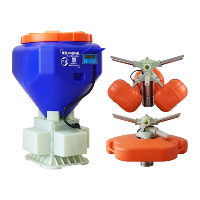
A Variable Frequency Motor Feeder can help aquaculture operators regulate feed delivery, adjust equipment speed, and coordinate feeding operations with changing production requirements. In modern fish and shrimp farming, feed distribution directly affects feed conversion efficiency, growth consistency, labor requirements, and water quality. A feeding system that delivers feed at a fixed rate may be unable to respond effectively to differences in fish size, stocking density, feeding behavior, or production stage. Variable-frequency control offers a way to make motor-driven feeding equipment more adaptable, provided the motor, feeder mechanism, and control strategy are designed as an integrated system.
For aquaculture equipment manufacturers, the technical objective is not simply to add a variable frequency drive (VFD) to a conventional motor. The complete system must deliver stable low-speed operation, adequate starting torque, predictable feed output, and reliable performance in humid, corrosive environments. These requirements become especially important when feeders operate for extended periods, serve multiple tanks or ponds, or need to respond automatically to feeding schedules and sensor signals.
The term Variable Frequency Motor Feeder can describe different equipment configurations depending on the manufacturer. It may refer to a feeder driven by a variable-speed motor and frequency converter, or to a motor-feeder assembly designed for adjustable feed delivery. Before specifying a system, the intended feeder mechanism, motor ratings, control interface, and operating environment should be clearly defined.
How Variable Frequency Control Regulates Feed Delivery
A variable frequency drive controls the frequency and voltage supplied to an AC motor, allowing the motor's rotational speed to be adjusted over a defined operating range. For a conventional induction motor, synchronous speed is related to the supply frequency and the number of motor poles. Actual shaft speed is slightly lower because of motor slip.
This speed-control capability provides a practical way to regulate the output of motor-driven feeding mechanisms. For example, in a screw feeder, changing the screw's rotational speed can change the volume of feed conveyed per unit of time. In a rotating disc feeder, motor speed can influence the rate and pattern of feed distribution, although the final result also depends on disc geometry, feed characteristics, and the arrangement of the discharge opening.
A simplified relationship for a feeder with stable mechanical conditions is that output tends to increase as the driving mechanism's speed increases. However, this relationship should not be treated as universally linear. Feed pellets can vary in diameter, density, moisture content, and surface friction. Hopper geometry, bridging, residual material, and mechanical wear can also affect the amount of feed discharged at a given speed.
Consequently, motor frequency alone is not a reliable measurement of feed quantity. If a feeding application requires precise dosing, the equipment should be calibrated by measuring actual output at representative speed settings and with the intended feed type. Where greater accuracy is necessary, a feedback mechanism such as a load cell or a suitable flow-monitoring arrangement may be required, depending on the system design.
Selecting the Right Motor and Variable Frequency Drive
Motor selection should begin with the mechanical load rather than the desired operating frequency alone. A feeder that uses a screw conveyor, rotary mechanism, or agitator may experience different torque demands during startup and steady operation. Feed accumulation, mechanical friction, and partial blockage can increase the load beyond normal running conditions.
The motor's rated power, voltage, current, frequency, insulation system, and permissible operating speed must be compatible with the feeder's duty cycle. The VFD should be selected to match the motor and the actual load characteristics, with appropriate consideration of output current, overload capability, ambient temperature, enclosure requirements, and supply conditions. Selecting a drive solely according to its nominal kilowatt rating can be insufficient if the feeder experiences frequent starts or high breakaway torque.
Low-speed operation deserves particular attention. When a standard self-cooled motor runs significantly below its rated speed, its shaft-mounted fan also slows down, reducing cooling airflow. Continuous operation at low frequency may therefore cause excessive motor temperature even when the mechanical load appears moderate. Depending on the duty cycle and speed range, the system may require a motor designed for inverter operation, an independent cooling fan, or a control strategy that limits continuous low-speed loading.
The drive's control mode also matters. Basic scalar control may be sufficient for a feeder with relatively stable torque requirements and moderate speed-control demands. Sensorless vector control can provide improved torque control over a broader operating range, depending on the motor and drive implementation. The appropriate choice should be based on startup behavior, speed stability, load variation, and required control precision rather than on a general assumption that the most advanced mode is always necessary.
For an aquaculture installation, the motor and drive must also tolerate the site's electrical and environmental conditions. Moisture, salt exposure, cleaning procedures, and condensation can affect equipment reliability. Enclosure protection, cable glands, grounding, ventilation, and corrosion-resistant components should be specified for the actual installation environment.
Matching Feeder Speed to Aquaculture Production Needs
Feeding requirements change throughout the production cycle. Juvenile fish may require smaller feed portions distributed more frequently, while larger fish may consume different quantities and pellet sizes. Shrimp feeding strategies can also vary according to biomass, water temperature, dissolved oxygen, and observed feeding activity.
A Variable Frequency Motor Feeder allows operators to adjust delivery speed to suit these changing requirements. At lower speeds, a feeder may provide a controlled flow for small portions or gradual distribution. At higher speeds, it can increase throughput when a larger quantity is needed within a limited feeding window. The useful speed range depends on the feeder's mechanical design and the characteristics of the feed being handled.
However, a lower motor speed does not automatically guarantee better feed utilization. If the feeder operates below its stable discharge range, feed may accumulate irregularly or be released intermittently. Conversely, excessive speed can distribute feed faster than the stock can consume it, increasing uneaten feed and potentially deteriorating water quality.
A practical setup process should establish several validated operating points. For each point, the operator measures the quantity of feed delivered over a known period, checks whether the distribution pattern is appropriate, and observes whether the equipment operates smoothly. The resulting calibration data can be used to define feeding programs based on biomass, feed type, and production objectives.
For multi-tank or multi-pond operations, consistent calibration is particularly important. Two feeders operating at the same frequency may deliver different quantities if their mechanical tolerances, hopper conditions, or feed characteristics differ. Periodic output checks help identify deviations before they materially affect feeding performance.
Integrating Timers, Sensors, and Automated Feeding Programs
Variable frequency control becomes more useful when it is connected to a broader feeding strategy. A basic installation may use preset speeds and timed operating periods. A more advanced system may receive commands from a central controller, farm-management platform, or sensor-based control system, depending on the available interfaces.
For example, a timer can activate a feeder at scheduled intervals, while the VFD controls the motor's operating speed during each feeding event. A programmable controller can select different speeds or operating durations for different production stages. Where compatible interfaces are available, the system can also exchange operating status, alarms, and command information with supervisory equipment.
Automation should distinguish between motor control and actual feed delivery. A drive may report that the motor is running even when a hopper is empty, a screw is blocked, or the feeder mechanism has become disconnected. If feed availability must be monitored, additional sensing may be required. Similarly, a motor overload alarm can identify abnormal electrical loading but may not explain whether the cause is a mechanical obstruction, bearing wear, or another fault.
The control design should include appropriate startup and shutdown behavior, overload protection, fault reporting, and recovery procedures. Automatic restart after a power interruption should be considered carefully because unexpected feeder activation may cause unintended feed discharge. The correct behavior depends on the installation and the operational risk assessment.
Energy Efficiency and Operating Cost
A VFD can reduce energy consumption when it allows a motor to operate at a lower speed instead of running continuously at full speed while the feeding mechanism is throttled or intermittently loaded. The actual savings depend on the motor's load profile, operating hours, control method, and the mechanical characteristics of the feeder.
It is important not to apply fan and pump energy-saving assumptions directly to every feeding mechanism. In a centrifugal pump or fan, power demand often decreases substantially as speed falls. A screw feeder or other positive-displacement mechanism may have a different relationship between speed, torque, and power. The energy benefit should therefore be verified using the feeder's actual operating data.
The strongest efficiency gains may come from matching operating time and output to real demand, reducing unnecessary continuous operation, and avoiding excessive feed delivery. Feed is a major operating expense in aquaculture, so accurate delivery can be economically significant even when the feeder's direct electricity consumption is relatively small.
A practical evaluation should compare electricity use, feed output, operating hours, maintenance requirements, and feeding consistency before and after a control change. It should also consider the VFD's own losses and any cooling or electrical components required by the installation. This provides a more realistic picture of total operating cost than looking only at the motor's rated power.
Reliability in Humid and Corrosive Aquaculture Environments
Aquaculture equipment frequently operates in environments with high humidity, water splashes, salt-laden air, cleaning chemicals, and temperature fluctuations. These conditions can affect motor insulation, electrical connectors, control cabinets, bearings, and mechanical transmission components.
The appropriate protection strategy depends on where each component is installed. A motor exposed to direct splashing may require a different enclosure and sealing arrangement from a drive mounted inside a protected electrical cabinet. Enclosure ratings should be verified against the actual exposure conditions, and they should not be interpreted as universal protection against every chemical, corrosion mechanism, or cleaning procedure.
Condensation is another concern. A sealed enclosure can still experience internal moisture when temperature changes cause water vapor to condense. Depending on the installation, suitable cabinet ventilation, anti-condensation heating, drainage, or humidity management may be necessary. Electrical terminals should be protected against corrosion, and cable routing should prevent water from entering enclosures through cable entries.
Maintenance planning should cover motor temperature, abnormal vibration, bearing noise, drive alarms, ventilation paths, and feeder output consistency. Regular checks of the hopper, discharge mechanism, and transmission system are equally important because mechanical wear can affect feed output even when the motor and drive remain electrically healthy.
Why Integrated Motor and Feeder Design Matters
A reliable Variable Frequency Motor Feeder depends on compatibility between the motor, VFD, transmission, feeder mechanism, and control logic. An oversized motor may increase initial cost without solving a problem caused by poor mechanical design. An undersized motor may struggle during startup or when feed accumulates. A capable VFD cannot compensate for an unstable discharge mechanism or unsuitable hopper geometry.
Jiangchen Electric Motor Co., Ltd. focuses on power equipment for aquaculture, combining motor manufacturing expertise with an emphasis on intelligent equipment and energy-efficient operation. For applications requiring adjustable feed delivery, the key technical considerations include the intended load profile, stable speed range, environmental protection, control integration, and the ability to calibrate output against real feeding requirements.
Before selecting a system, confirm the motor's rated parameters, the drive's compatibility and overload capability, the feeder's output range, and the available control interfaces. Ask how the equipment performs at low speed, how it responds to a jam or overload, and what environmental protection is provided. If precise dosing is required, request measured output data across the intended operating range.
A properly engineered Variable Frequency Motor Feeder can support more flexible feeding schedules, improve control over feed delivery, and reduce unnecessary operation. Its long-term value depends on matching electrical and mechanical design to the actual aquaculture application, validating feed output under real conditions, and maintaining the equipment as part of the farm's wider production system.
www.jiangchenmotor.com
Foshan Jiangchen Electric Motor Co., Ltd.
About Author