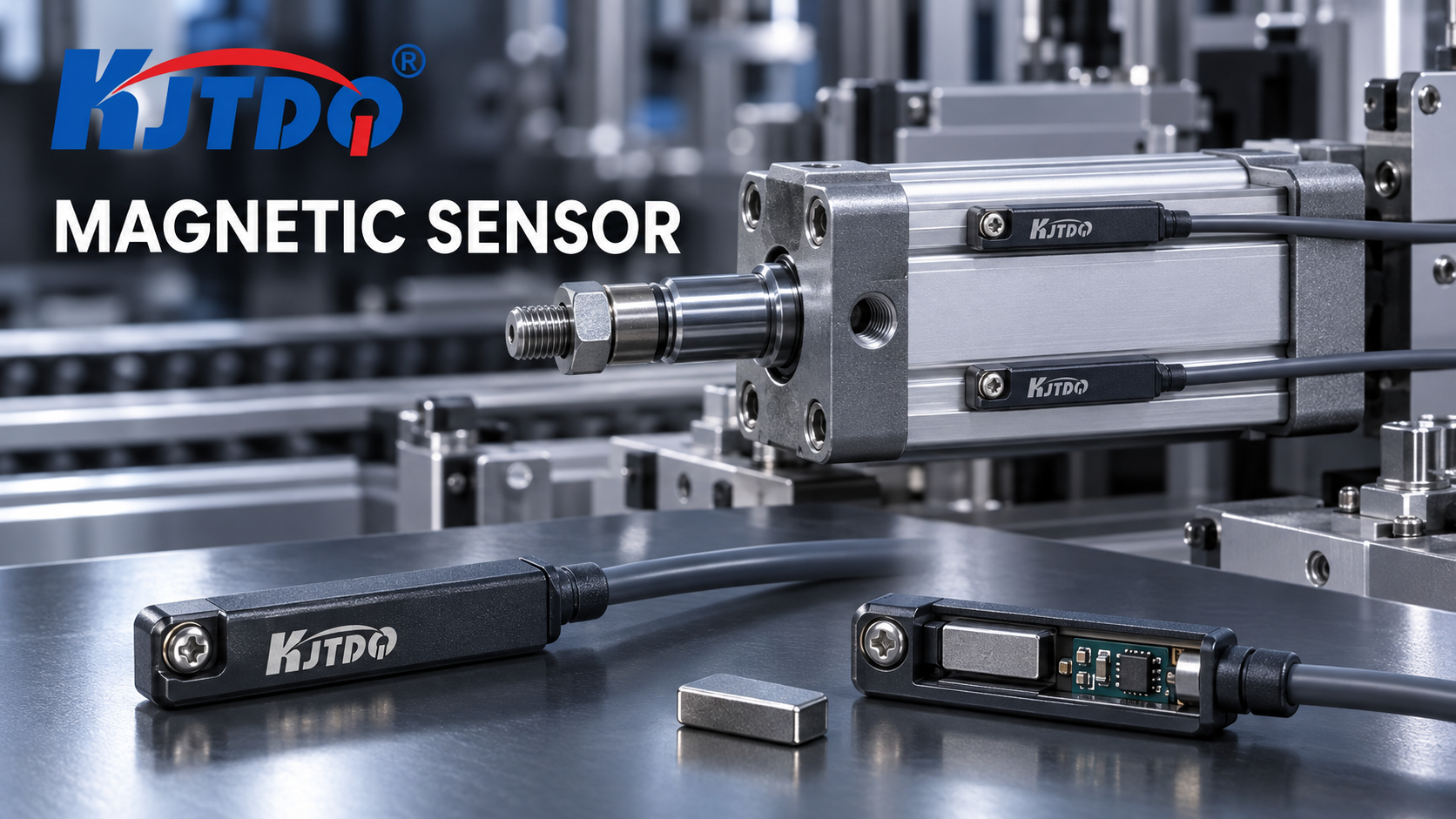
A magnetic cylinder sensor detects the permanent magnet fitted to the piston, sensing it through the cylinder wall from the mounting slot — so it is the natural method for standard pneumatic cylinders with piston magnets, giving contactless, wear-free end-position feedback without any external target. An inductive proximity sensor detects a metal target and cannot see the piston through a metal wall; it suits cylinders without piston magnets where an external metal flag or machine part serves as the target, or aluminum-body cylinders where the sensing geometry works. Choose magnetic sensing when the cylinder has a piston magnet (most do); choose inductive sensing when it does not or when the detection target is a machine element rather than the piston itself. KJT Sensors supplies both families — magnetic sensors in groove, rice-cylinder, circular-cylinder and pull-cylinder mounting types — with switching point, hysteresis and output confirmed for the specific model.
Key Takeaways
- The deciding question is one word: magnet. Does the cylinder contain a detectable piston magnet? Yes → magnetic sensing through the wall. No → inductive sensing of an external metal target.
- Magnetic sensing is contactless through the cylinder wall: KJT Sensors magnetic sensors detect permanent magnets "of all strengths mounted on all common cylinder pistons," wear-free, short-circuit-proof, IP67 (manufacturer-stated).
- Inductive sensing cannot see through metal. An inductive sensor detects the piston magnet's field only by coincidence — its own principle requires a metal target in open air; sensing through a steel cylinder wall is not its operating mode.
- Mounting type is a cylinder property, not a preference: groove (C-slot/T-slot), round-body tie-rod, circular and pull-cylinder formats each need their sensor mounting — KJT Sensors offers all four types.
- Switching point and hysteresis must be verified per model: they determine where the switch actually trips along the piston's travel and how much magnet movement reverses before it releases.
- For a sensor already switching twice or losing the end signal in service, that is a diagnosis problem with its own treatment (cylinder magnetic-sensor troubleshooting guide).
What Each Method Actually Senses
Magnetic sensing: the piston's own field
A magnetic cylinder sensor (reed or Hall-based) is mounted on the cylinder body — typically in the groove — and detects the permanent magnet ring carried on the piston as it passes. KJT Sensors' magnetic sensors "work electronically and can precisely detect permanent magnets of all strengths mounted on all common cylinder pistons," and are wear-free, short-circuit-proof, durable and rated IP67; versions exist for welding areas, explosion-proof areas and with analog output (manufacturer-stated, Magnetic Sensor).
The KJT Sensors magnetic range covers four mounting formats — groove type, rice-cylinder type, circular-cylinder type and pull-cylinder type — each matching a cylinder family's rail or body geometry (confirmed live on the category page). Hall-effect variants extend the same magnetic principle to rotation and speed detection of magnetic targets, but for cylinder duty the magnetic switch is the workhorse.
Two engineering quantities govern the result:
- Switching point: the piston position at which the sensor output changes state. It depends on magnet strength and position, sensor sensitivity, and the wall between them.
- Hysteresis: the difference between the switch-on point and the switch-off point as the piston reverses. It prevents output chatter when the piston parks exactly at the switch point.
Both are model properties to be verified on the actual cylinder — which is why KJT Sensors' selection guidance for cylinder applications asks for the cylinder brand, groove type, magnet-ring condition and an installation photo.
Inductive sensing: a metal target in the open
An inductive proximity sensor generates a high-frequency electromagnetic field and detects the eddy currents a metal target introduces. It is the standard non-contact answer for metal parts — and the subject of its own comparison for metal versus non-metal targets.
For cylinder end-position feedback, inductive sensing is the choice when the detection target is not the piston magnet but an external metal feature: a flag on the piston rod extension, a clevis, a cam on the mechanism the cylinder drives. Its constraint is equally clear: the sensing field does not pass usefully through a metallic cylinder wall, and the sensing distance is defined against a specified metal target in open air. On a standard tie-rod cylinder, an inductive sensor watching for "the piston" through the wall simply does not operate; on a rod-extension flag or driven-mechanism part, it works exactly as its datasheet says.
Same-Dimension Decision Table
| Dimension | Magnetic cylinder sensor | Inductive proximity sensor |
|---|---|---|
| What it detects | Permanent magnet on the piston, through the cylinder wall | Metal target in open air near the sensing face |
| Cylinder requirement | Cylinder must contain a detectable piston magnet (standard on most pneumatic cylinders) | No cylinder requirement; needs an external metal target (flag, rod extension, driven part) |
| Mounting | In/on the cylinder: groove, rice-cylinder, circular, pull-cylinder types | Free-positioned at the target's travel path, at rated sensing distance |
| Sensing through the cylinder wall | Yes — that is the operating mode | No — the field does not usefully penetrate a metal wall |
| Switching-point placement | Along the piston travel, set by magnet/sensor geometry; verified per model | At the target's approach, set by sensing distance to the metal target |
| Hysteresis | Magnet-based; prevents chatter at the switch point — model property | Target-based; same role, different values — model property |
| Wear | Wear-free, contactless (manufacturer-stated) | Wear-free, contactless |
| Interference considerations | External magnetic fields, magnetized fixtures, welding environments (weld-area versions available) | Surrounding metal reducing effective distance; weld-field-resistant inductive variants exist |
| KJT Sensors variants | Groove/rice/circular/pull mounting; welding-area, explosion-proof, analog-output versions (manufacturer-stated) | Multiple inductive series incl. high-temperature, NAMUR, weld-field-resistant |
| Typical failure mode | Double-switching on one pass, end-signal loss (diagnosis: https://www.kjt-sensors.com/show-27196.html) | False trigger from surrounding metal, distance shortfall on small targets (diagnosis: https://www.kjt-sensors.com/show-27195.html) |
Decision Sequence for Cylinder End-Position Feedback
- Open the cylinder datasheet: is there a piston magnet? Standard pneumatic cylinders almost always carry one. If yes and the magnet is healthy, magnetic sensing is the default — no target hardware to design, no alignment to maintain.
- Confirm the mounting format. C-slot/T-slot groove, round tie-rod body, circular or pull-cylinder format — the sensor's mounting type must match the cylinder's. Mixed-brand fleets often carry mixed formats; KJT Sensors' guidance asks for the cylinder brand and groove type for exactly this reason.
- Define where the switch point must sit. End positions, intermediate positions or both. The switching point and hysteresis of the chosen model determine how close to the physical end the electrical signal lands.
- If there is no magnet — or the magnet cannot be relied on — design an inductive target. A metal flag on the rod extension or a part on the driven mechanism, sized for the sensor's rated distance with margin for the real target geometry.
- Check the environment. Welding spatter zones and explosion-proof areas have dedicated magnetic-sensor versions (manufacturer-stated); weld-field-resistant and high-temperature variants exist on the inductive side; strong external magnetic fields near the cylinder need evaluation for the magnetic route.
- Match the output to the controller. PNP/NPN and NO/NC selection follows the same PLC-input discipline as any switching sensor.
What to Send for a Selection Recommendation
KJT Sensors' cylinder-sensor selection guidance asks for exactly these inputs — reproducing them saves an inquiry round:
- cylinder brand and model, and whether its piston magnet is intact (for magnetic sensing);
- groove/body type (groove, rice, circular, pull) or the mounting photo;
- required switching positions (end / intermediate) and tolerance;
- supply voltage, output type (PNP/NPN, NO/NC) and controller input;
- environment: welding area, explosion-proof area, oil, dust, vibration, temperature;
- cable or connector form and length.
The same application-information discipline applies to any sensor selection — the general checklist is covered in the sensor application information guide, and the broader position/travel context (limit switches included) in the travel-detection comparison.
KJT Sensors Options
| Application situation | Recommended KJT Sensors path | Confirmed scope |
|---|---|---|
| Standard cylinder with piston magnet | Magnetic cylinder sensor — groove type (and rice/circular/pull formats) | Detects magnets of all strengths on all common cylinder pistons; wear-free, short-circuit-proof, IP67; welding-area, explosion-proof, analog-output versions (manufacturer-stated) |
| Magnet cylinder in welding environment | Welding-area magnetic sensor version | Listed capability on category page (verified 2026-10-10) |
| No piston magnet / detect the driven mechanism | Inductive proximity sensor + metal target | Multiple inductive series (category page verified 2026-10-10); distance per model datasheet |
| Rotation/speed of magnetic targets | Hall-effect sensor | Detects motion, position and speed of magnetic materials (manufacturer-stated) |
Switching point, hysteresis, output and mounting dimensions are confirmed for the specific model. Pricing is quoted by model and project requirements, based on mounting structure, output type, protection requirements and quantity.
Limitations and Validation Needs
- "Permanent magnets of all strengths on all common cylinder pistons" is a manufacturer statement of scope; the actual switching point on a specific cylinder depends on that cylinder's magnet and wall, and must be verified on the machine.
- Switching-point and hysteresis values are model properties not published at category level; no numeric values are claimed in this article.
- Inductive sensing distances assume defined target conditions; rod-extension flags must be sized and verified for the chosen model.
- Explosion-proof and welding-area versions must be selected against the actual area classification and zone requirements.
- A sensor that double-switches or loses the end signal after installation is a troubleshooting case (cylinder magnetic-sensor troubleshooting guide), not a selection redo.
FAQs
Does the cylinder contain a detectable piston magnet? Most standard pneumatic cylinders do — it is the mechanism magnetic cylinder sensing is built on. Check the cylinder datasheet or, for an existing installation, slide a magnetic sensor along the body and watch for a switch. KJT Sensors' sensors are stated to detect permanent magnets of all strengths on all common cylinder pistons (manufacturer-stated); the verification that matters is on your specific cylinder.
Can an external metal flag be used instead? Yes — that is precisely the inductive route, for cylinders without usable piston magnets or when the detection target should be the driven mechanism. Design the flag (or use a rod-extension feature) as a metal target within the inductive sensor's rated distance, with margin for the real target size and material.
Which mounting position and switching-hysteresis data must be verified? Three items: (1) the mounting type matches the cylinder format — groove, rice-cylinder, circular or pull-cylinder; (2) the model's switching point places the electrical signal where the control needs it along the piston travel; (3) the hysteresis is wide enough to prevent chatter but narrow enough to confirm the position. All three are model properties verified on the actual cylinder.
Why not just use an inductive sensor on the cylinder wall? An inductive sensor's field is defined for a metal target in open air; it does not usefully pass through a metallic cylinder wall to reach the piston. Inside a wall-mounted scenario it would switch on the wall itself, not the piston. Through-wall piston detection is the magnetic sensor's operating mode.
What if the sensor switches twice or drops the end signal in service? That symptom pattern — double switching on a single pass or losing the end signal — has specific causes (magnet strength, switching-point placement, hysteresis too narrow) with its own diagnostic sequence in the cylinder magnetic-sensor troubleshooting guide.
Do magnetic sensors work in welding areas or hazardous zones? KJT Sensors lists welding-area and explosion-proof versions of its magnetic sensors, plus analog-output types (manufacturer-stated). The applicable version must be selected against the actual environment and, for hazardous areas, the site's area classification.
Conclusion
Magnetic versus inductive cylinder-position sensing is decided by what there is to detect. A piston magnet — present on most cylinders — calls for a magnetic sensor in the matching mounting format, sensing through the wall with zero wear. No magnet, or a decision to detect the driven mechanism instead, calls for an inductive sensor and a real metal target in open air. Verify the switching point and hysteresis on the actual cylinder for either route, match the output to the controller, and use the environment-specific versions where the site demands them.
Sources
- KJT Sensors, Magnetic Sensor (category page, verified accessible 2026-10-10): https://www.kjt-sensors.com/list-cgycgq.html
- KJT Sensors, Proximity Sensors (category page, verified accessible 2026-10-10): https://www.kjt-sensors.com/list-jjkg.html
- KJT Sensors, Magnetic and Hall-Effect Sensor product data and selection guidance (internal knowledge base, Grade B manufacturer-stated)
https://www.kjt-sensors.com/
KJT Sensors
About Author